Design for Manufacturing (DFM): Principles, Processes, and Best Practices
What Is Design For Manufacturing (DFM)?
Design for Manufacturing (DFM) is the practice of refining product designs so they can be produced reliably and cost-effectively at scale using standard manufacturing methods.
For instance, a prototype that works on a 3D printer may not be feasible for mass production with injection moulding. DFM bridges that gap, translating design intent into manufacturable detail.
DFM is most valuable when it starts early in the design process. While less critical during rapid prototyping, incorporating good basic Design for Manufacturing principles into the design of your prototype parts before production helps prevent costly mistakes, reduces redesigns, and improves the chances of a smooth transition to large-scale manufacturing.
DFM vs. DFA vs. DfAM
Design for Manufacturing (DFM), Design for Assembly (DFA), and Design for Additive Manufacturing (DFAM) are interconnected but distinct. Each addresses a different stage of moving from concept to production.
- Design for Manufacturing (DFM) ensures parts can be manufactured efficiently and at scale using standard processes.
- Design for Assembly (DFA) focuses on making assemblies and sub-assemblies faster, easier, and more reliable to assemble. It considers inspection, testing, and assembly challenges, often adding features that streamline the process. DFA becomes critical at higher production volumes where labour efficiency directly impacts cost.
- Design for Additive Manufacturing (DFAM) optimizes designs specifically for 3D printing or other additive methods. Unlike injection moulding, additive doesn’t require draft angles, moulds, or uniform wall thickness. Instead, it emphasizes orientation, surface quality, and strength relative to the build direction. DfAM is essential for low-volume, high-cost parts where traditional manufacturing isn’t economical.
Ultimately, DFM, DFA, and DFAM activities must strike a balance between technical feasibility and economic reality. The one that takes priority depends on scale, process, and return on investment.
Why DFM Matters When Moving from Prototype to Production
From looks-like to production-intent: Why the type of prototype matters
Prototypes can take many forms throughout the design process, each serving a different purpose. For example:
- Quick functional prototypes, such as cardboard, tape, or simple materials, allow teams to role-play, explore usability, and test ideas rapidly at minimal costs.
- Looks-like prototypes resemble the final product visually but lack functionality. They are often used to align stakeholders around a shared vision of what the product will become.
- Production-intent prototypes represent the design as it is intended to be manufactured. While not made with final tooling, they are the closest estimate of the production device. Refinements may still occur once full manufacturing begins, but these prototypes provide the strongest foundation for validating performance and manufacturability at scale.
Production-intent prototypes are especially valuable because they allow teams to evaluate Design for Assembly (DFA) in practice. Unlike CAD models, they reveal real-world challenges like gravity, alignment, or sequence of operations. For example, a prototype may expose that a connector must be inserted before a circuit board can be seated.
What production-intent prototypes validate
- Parts can be produced with their intended manufacturing methods (e.g., injection moulding for plastics, PCB fabrication for circuit boards).
- Assembly processes are efficient, feasible, and scalable — not just theoretically possible in CAD.
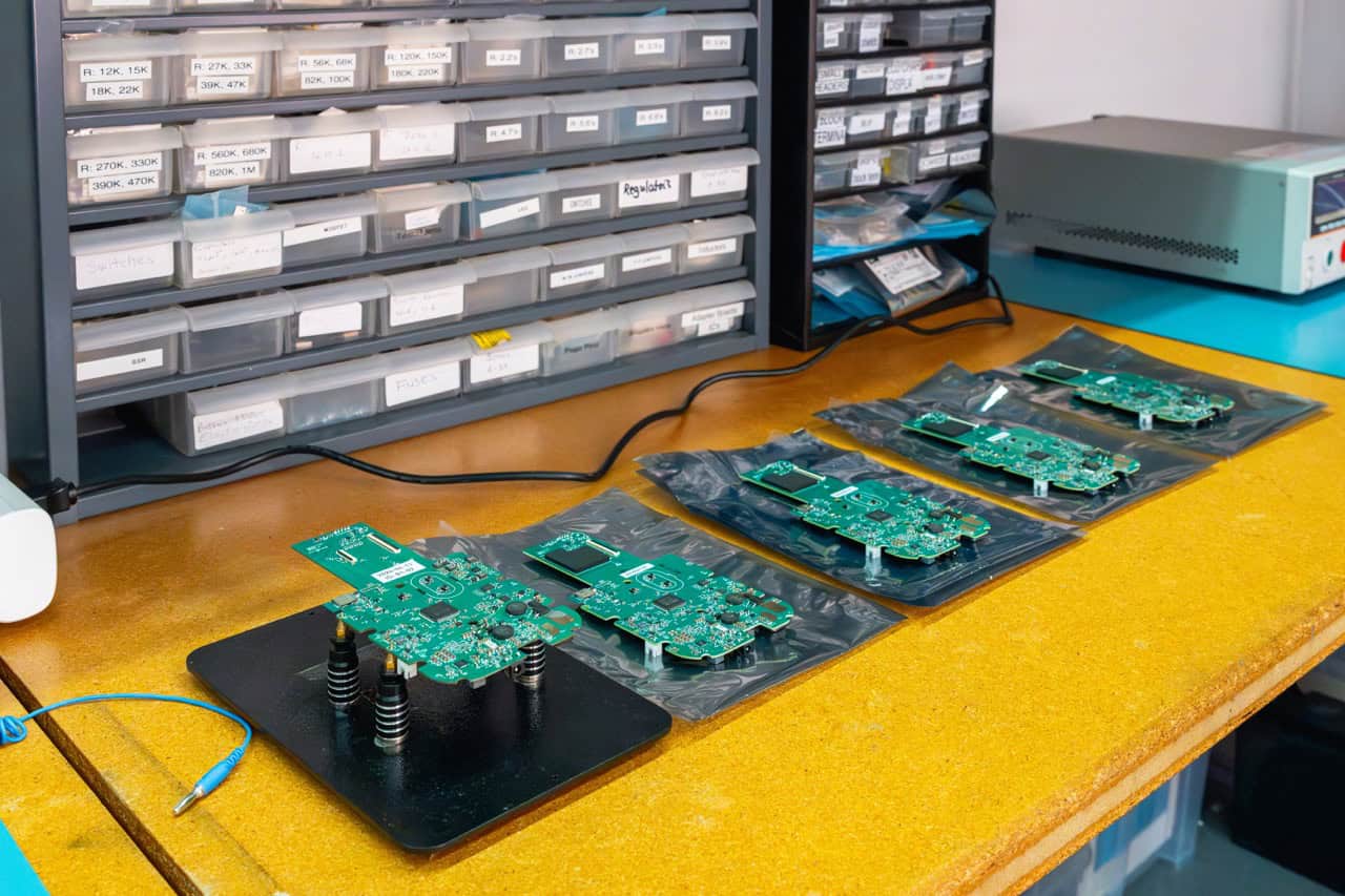
Key considerations for PCB production-intent prototypes
Supply-chain resilience
Choose component packages that are proven and widely available. For critical parts, always specify approved alternates—this reduces the risk of delays if something goes out of stock.
Traceability and serviceability
Integrate clear markers and programming ports so every PCB can be fully tested, individually serialized, and traced back to its production lot – making recalls and field debugging easier to manage.
Process repeatability and automation
Include standard features like fiducials, polarity markings, and reference designators. These are essential for accurate optical inspection (AOI) and smooth automated assembly.

The prototype trap
Prototypes are not always perfect predictors of production. They are often rougher than the final manufactured parts, but they can still reveal areas of weakness. The rule of thumb:
- If something fails in prototype, it will likely fail in production.
- If something passes in prototype, it’s not guaranteed to succeed at scale.
That’s why Design for Manufacturing must be considered early and tested often. It prevents costly redesigns and ensures the product can survive both manufacturing and real-world use.
Principles and Guidelines of an Effective DFM
Design for Manufacturing principles vary depending on the manufacturing process, but the goal is universal: design parts that can be produced efficiently, reliably, and at scale. For example, in:
- Injection moulding: avoid sink marks from uneven walls, add proper draft angles for part release, and minimize undercuts that require complex shutoffs.
- Circuit boards: ensure mechanical components like switches are well-supported to prevent field failures, and follow IPC standards—such as IPC‑6012E for rigid printed circuit boards, and IPC‑2612, 2614, and 2615 for schematics, fabrication drawings, and dimensioning/tolerancing, respectively—to maintain quality and reliability.
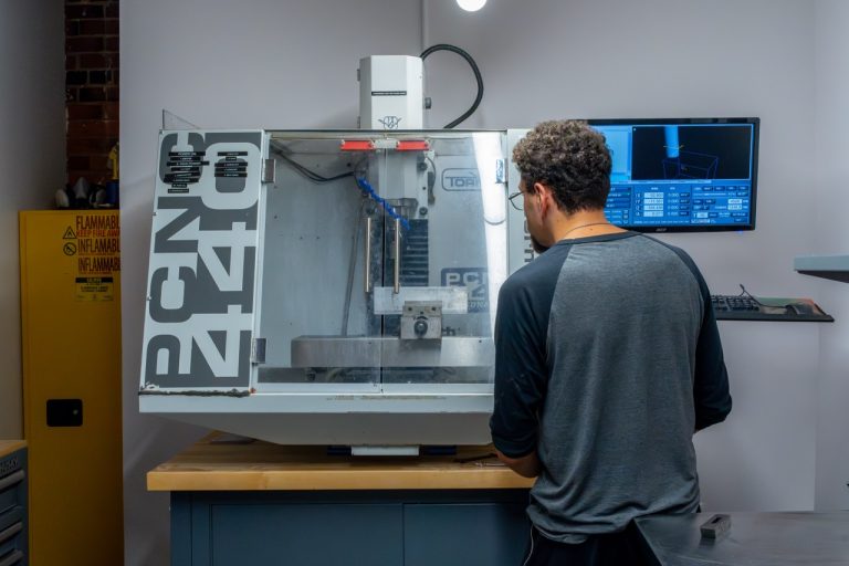
- Metal machining/casting: manage tolerances, tool access, and cost trade-offs in CNC milling or casting.
Best practices are well-documented and can often be learned through experience or reference. But DFM isn’t static — it evolves alongside manufacturing technologies. Additive manufacturing illustrates how DFM evolves with new technologies. It removes traditional constraints like tooling and draft angles, and can dramatically shorten lead times compared to moulding — a process that may require 60–90 days and costly tooling. However, it introduces new considerations such as build orientation, layer adhesion, and surface finish.
Staying current with evolving processes ensures the right manufacturing choice — reducing cost, accelerating time-to-market, and delivering products that succeed for both the business and the customer.
Dangers of Ineffective DFM
Poor DFM decisions often lead to low-quality parts, but they can also quietly drive up your cost of goods sold (COGS), introduce hidden labour burdens, or make scaling impossible. Here are three common risk areas that show how Design for Manufacturing, done wrong, can impact both product reliability and long-term cost.
Performance failures that don’t show up in CAD
Injection moulded parts
Injection moulding requires careful control of wall thickness and flow. If wall thickness is inconsistent, the plastic cools unevenly; thick sections cool more slowly than thin ones, causing sink marks or surface depressions. Holes and other features can also create knit lines – visible seams or weak points – where flows meet.
Circuit boards
While printed circuit boards (PCBs) can handle thousands of surface-mount components with precision, mechanical features such as switches and buttons require special care. A push button may look fine in CAD, but pressing it 10,000 times can crack the board if the design doesn’t properly support the switch.
Avoiding these failures means anticipating stress points early, testing aggressively, and reinforcing weak areas before production. And performance isn’t the only risk. Regulatory compliance may have been confirmed on a single prototype, but maintaining that compliance across 10,000+ units requires consistent manufacturing, tight tolerance control, and robust quality systems. Variability in component specs or layout execution can easily push a once-compliant design out of spec.
Documentation errors that derail production
Even small documentation errors can carry major production consequences. A common example: marking a required component as “Do Not Populate” (DNP) in the electronics BOM. If that error isn’t caught before assembly, it can lead to weeks or even months of manual rework, scrapped boards, or failed test procedures—all of which could have been avoided with proper review and file handoff discipline.
DFM cost traps that backfire
Sometimes, DFM mistakes come from misjudged cost-saving assumptions. For example, choosing a custom part over an off-the-shelf one might seem cheaper on paper—but if it requires more manual assembly, non-automatable QC testing, or slows down production, it can quietly balloon your COGS.
These hidden costs often stem from a narrow focus on component price, without accounting for downstream factors like assembly labour, QC testing, or yield variability. Designing for true manufacturability means thinking holistically about cost—not just what’s on the BOM, but how the product will actually be built and tested at scale.
The real cost of getting DFM wrong
The most dangerous consequence of poor DFM is that a product may work fine as a prototype but fail in the hands of customers.
If weak points in the design aren’t identified, tested, and reinforced early, those failures will only emerge in the field. At that stage, the costs are enormous: warranty claims, recalls, reputational damage, and lost customer trust. In many cases, this can be devastating to a company.
That’s why production design must anticipate how a product will survive its entire lifecycle—not just its first use. And lifecycle failure isn’t always mechanical. Sometimes it shows up in how a product is deployed. For example, many medical wearables require calibration before they can function reliably in the field. If the design doesn’t support automated calibration, scaling becomes painful: manual tuning adds cost, delays deployment, and introduces inconsistency across users and body types.
DFM isn’t just about manufacturing — it’s about making sure the product survives the real world. Rigorous testing and thoughtful design are what keep costly failures from reaching your customers.
The DFM Process
When it starts
Most products are designed with at least a rough sense of the manufacturing process. However, the right time to actively apply DFM is when the product vision begins to take tangible shape— as materials and intended production volumes are defined.
- Materials determine which manufacturing processes are feasible.
- Production scale dictates whether a process should be optimized for low-volume flexibility or high-volume efficiency.
Together, these choices set the manufacturing path, and in turn, the DFM principles needed to ensure designs can be produced reliably, cost-effectively, and at the desired scale.
The process at Cortex
We structure product development into phases, with DFM playing a central role in the transition from Production-intent Prototype (Phase 3) to Production Design (Phase 4).
Phase 3: Production-intent prototype
By the end of Phase 3, the product should both look and function like the final design, though it isn’t yet optimized for production. At this stage, the intended manufacturing process should already be identified, even if all DFM details aren’t finalized. Prototypes are often built for simplicity and testability. For example, circuit boards may be mounted with screws so they can be removed and adjusted easily, even though this isn’t production-friendly.
Phase 4: Production design (DFM)
In Phase 4, the focus shifts from prototypes to designing for manufacturability and assembly at scale. Features that were useful during prototyping — like screw mounts — may be replaced by production-friendly alternatives, such as snap fasteners. While a snap feature might fail in repeated prototyping, in production, it only needs to work once.
In short, Phase 3 proves the product concept, while Phase 4 ensures it can be produced reliably and efficiently at volume. Knowing the intended process early, even before all DFM details are finalized, helps prevent costly surprises as the design moves toward scale.
How long does DFM take?
DFM typically accounts for 10–20% of the total Phase 4 effort. The length of Phase 4 varies with product complexity, usually spanning 1 to 6 months. Its purpose is to refine details, resolve unexpected issues, and ensure the design is truly production-ready, closing the gaps between a design that works in principle and a design that can succeed in the market at scale.
The timing is important: doing DFM too early often means rework, since designs and processes continue to evolve before Phase 4. But if done at the right stage, DFM ensures the final product can be manufactured reliably without costly redesigns.
Memoir from the CEO – The manufacturing stage
One of the most rewarding milestones in product development is reaching manufacturing after DFM has been done right. At this point, the design leaves the office and enters the factory floor.
Watching steel being cut to form an injection mould for a design you helped detail is both humbling and exhilarating. Toolmakers and engineers bring the design to life, using techniques like EDM (electrical discharge machining) to shape copper and steel into the massive tool that will produce thousands of parts.
When that tool runs its first injection moulding shots, it’s a critical milestone. Everyone in the value chain — from design to tooling to manufacturing — holds their breath to see whether those parts are close to the final intent. If the parts align with the design intent, it’s a powerful validation that the design process worked and that collaboration across disciplines paid off.
It’s the moment when the product stops being lines in CAD and starts becoming real at scale — and it’s always one of the most exciting parts of the journey.
Common Mistakes in Design for Manufacturing
Believing you’re designing for manufacturing when you’re actually designing for prototyping or convenience.
During early development, it’s natural to prioritize features that make debugging easier — extra connectors, test points, or interchangeable components. These speed up iteration but add unnecessary cost and complexity if carried into production.
A screw and brass insert might make sense in Phase 3, since snap fits often fail under repeated testing. But in production, where parts are assembled once, snap fasteners are cheaper, faster, and more scalable.
Assuming prototype plastics behave like production plastics
Large parts machined or 3D printed in prototype may seem stable, but when injection-moulded, they may cool unevenly or develop residual stresses that cause them to warp or deform. Without anticipating these effects, parts that looked perfect in CAD won’t fit in production. Experienced designers add alignment features or surrounding supports to avoid these failures.
Ignoring compliance until it’s too late
Treating compliance (especially EMC/EMI) as an afterthought is another expensive mistake. A device that works in prototype may fail emissions testing after tooling is complete. At that point, redesigning is often too costly, forcing teams to add “band-aid fixes” like internal shielding, ferrite beads, or patched cable harnesses.
Assuming identical performance across 10,000 units
Just because a component works in one prototype doesn’t mean it will behave identically across all units. For precision sensing or optical applications, it’s critical to account for component tolerances to ensure consistent functionality across 10,000+ devices.
The Bigger Picture in Design for Manufacturing
DFM isn’t only about producing parts and assembling them efficiently. It also includes designing for compliance. Investing the engineering effort early can save enormous cost, time, and frustration later, while protecting product quality and user trust.
Design for Manufacturing requires shifting perspective from “what makes my development process easier” to “what makes the product manufacturable, scalable, and user-ready.” Without that shift, teams risk carrying prototype conveniences into mass production, creating unnecessary expense and inefficiency.